How to identify cavitation in globe control valves, understand its root causes, and prevent damage through correct valve sizing and trim selection.
Cavitation is one of the most damaging phenomena in control valve service. It occurs when the local pressure in the liquid drops below vapour pressure, causing vapour bubbles to form, then violently collapse as pressure recovers.
Signs of Cavitation
- Loud crackling or rattling noise (similar to gravel passing through the valve)
- Rapid erosion of valve body and trim surfaces
- Vibration in the downstream pipework
- Reduced flow capacity over time
Root Causes
Cavitation depends on three factors: 1. High pressure differential across the valve 2. High inlet pressure relative to the vapour pressure of the liquid 3. Valve Cv and style — some valve styles (e.g. single-stage globe) are more prone to cavitation
Prevention Strategies
1. Anti-cavitation trim: Multi-stage pressure recovery trims reduce peak velocity and limit pressure drop per stage, keeping local pressure above vapour pressure.
2. Correct Cv sizing: Over-sized valves operating at low opening percentages are especially prone. Correct sizing keeps the valve in the 40–80% open range.
3. Downstream back-pressure: Increasing downstream pressure raises the critical pressure ratio, reducing cavitation tendency.
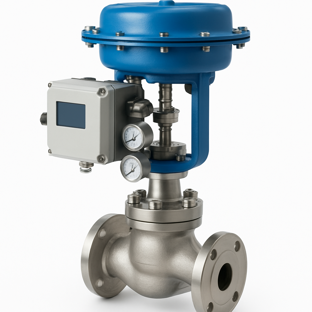
4. Cage-guided trim: Cage-guided globe valves allow easy trim replacement and protect the valve body from erosion.
AIRA's Series 500 anti-cavitation control valves use a patented multi-hole cage design validated to ISA 75.23 for cavitation service.
AIRA Euro Automation's engineering team publishes technical guides and application notes based on 30+ years of industrial valve manufacturing experience.